FX's Projects
Musings involving electronics, systems, and stuff hackers care about.
An oddball from the vault - surprizing joint cinematics
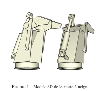
Here is an odd one. Look at that gem! Straight from the vault and now more than 10 years old.
In preparation for a Master’s degree, it appeared like a very good idea to join a bit of fun to a specific purpose. This funny paper, warts and all, was about describing a snow blower’s chute elevation mechanism.
The link with robotics will be apparent if you consider the problem of joint rotation and localisation, even though in this specific case only one degree of freedom is considered.
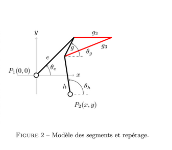
The problem to solve was to identify a working configuration, in short establishing the length of the $h$ link and its pivot mounting point location $P_2$ before the welder was switched on.
Why ?
Why oh why, you ask? The shallow answer is easy: two birds with one stone (two wins in one move, no birds were harmed…):
- configuring and testing a $\LaTeX$ tool chain for an incoming Master’s degree memoir
- designing a snow blower hydraulic actuated chute in one pass
The first goal was clear and the result is the attached .pdf report. It looked the part and got me enrolled, so that’s that…
As for the chute, and looking with envy at the neighbor’s machines, it became clear that the new (to me) snow blower from the 1970’s it came attached to was a bit lacking in features. The chute was fixed and mounting and dismounting the tractor was not only tedious, but also dangerous.
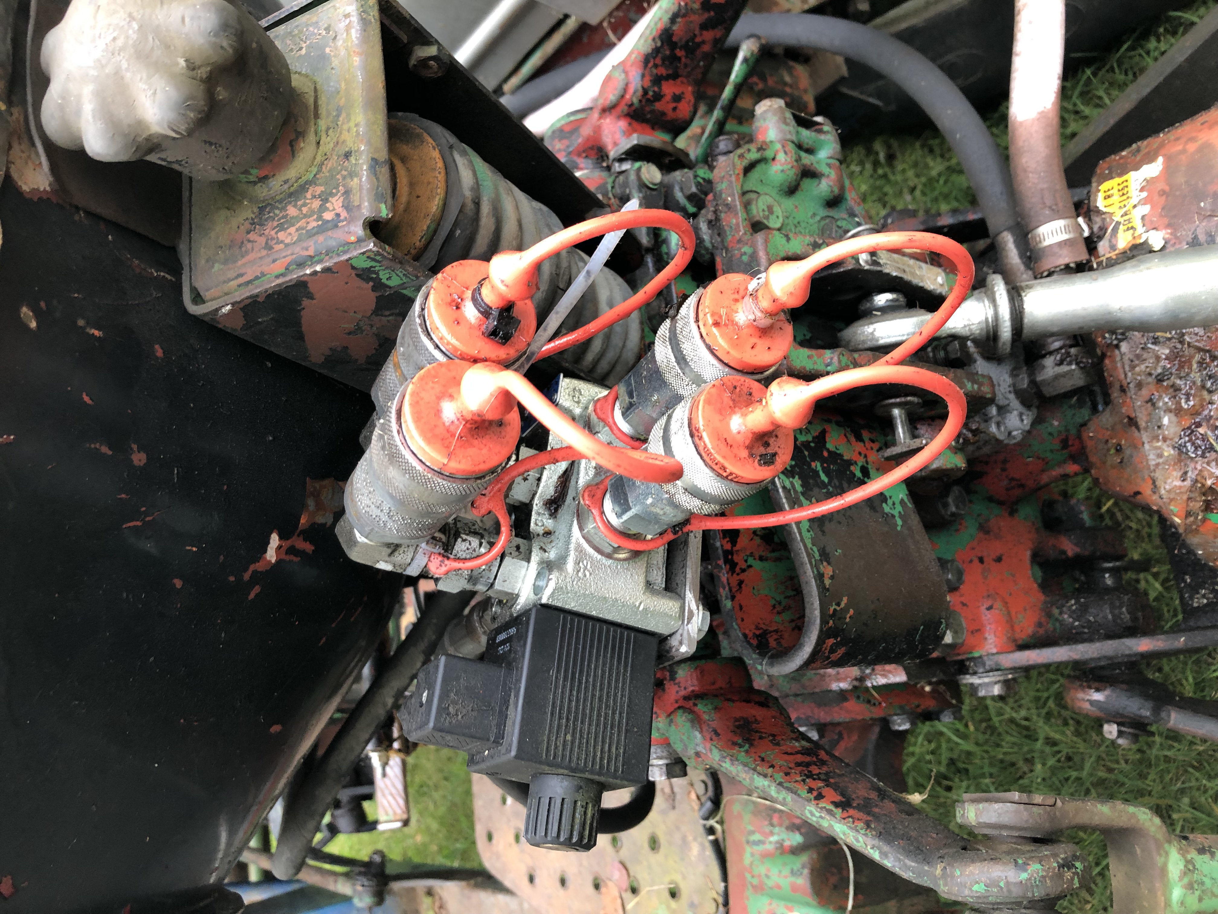
The auxiliary hydraulics of my old White 1370 were thus updated with an electrostatic derivation valve and two functions were now available. The capacity was about to be interfaced to the snow blower: chute rotation and elevation.
I had to configure the elevation mechanism and somehow attach it to an hydraulic actuator. Ideally at the proper location. On the first try.
Chute rotation
The rotation implementation went fast as a hydraulic cylinder pivoted an arm from which a cable was attached. That part was found as a used unit. The cable snugly fit over the chute with a few turns over the bottom cylinder section.
No real effort was made to plan that part of the design, as the tension in the cable was adjustable with a turnbuckle while the rotation center was easily adjusted with a screwed clamp. A few dabs of grease and some appropriately welded guides and an adjustable finger on top of the frame of the blower and the chute was rotating smoothly and with good span. That part of the project was eyeballed and it turned out great.
Chute elevation … Oops!
The chute elevation required more thoughts. A lot of it. Cylinder in hand, it was clear that the output angle swing would not enable sending the snow where it needed to go, especially when the lower angles were considered. Sending the white stuff directly on the ground around the tractor was very desirable and not really an option initially with the original, one hinged flap.
The main issue in adding the second flap was to select the position and length of the linkage $h$, as the movement of the second articulated flap, the one at the tip of the chute, could place it in very weird configurations. Metal bending configurations, that is. Don’t ask me why I know…
Math, force summation and two surprises!
The trick to solve the problem was to lay out the limbs on a coordinate frame and write down the force equilibrium equations for both axis. This yielded a set of parametric equations and the relative movement of the limbs was properly described with the output angle being described as a function of the input angle and the various design parameters.
In all humility, here is the resulting paper. It is in french, but the math should be easy to grasp nonetheless. In all cases, the main takeaways are summed up following the document.
(Disclaimer: Please note that I am no longer a registered engineer and that my coordinates have changed since writing this, so you can reach me on my LinkedIn instead if you want.)
A parameter space was found and then, as a surprise, the system revealed a few of its properties.
Double down
The first surprise was that the output angle was, essentially, the double of the input angle. That’s it. That is how you can flip the snow out of the blower and send it back down without bogging the fan. You have three surfaces to play with: the fixed chute part that guides the snow up to the sky, the first mobile flap that bends it to horizontal (watch it, the windows!), then the last part connected to the member $h$ that doubles the effective angle, sending the snow back down.
So, it came slowly to me that the snow blower had a chute elevator set with a gain of $6dB$. Yup, that also cracked me up at that time.
Vise Grips?
Unbeknownst to me, it turned out that the linkage was part of a large category of machine elements known as a “four bar linkages” with one degree of freedom. They come with predictable characteristics, they told me.
Looking at the design space, one can recognize a set of parameters that can be tested for a Grashof inequality to determine if the shortest link can rotate freely around its axis. Fascinating! And for those who are interested in learning more about this, I found a video that came out after this project and that would have saved me a lot of time and confusion: Mechanical Design - Four Bar Linkage
Conclusion
So I now recognize that the thing to avoid was a Grashof Inversion. The kicker is that this is exactly what you would want for your pair of Vise Grip pliers! Not so much for your blower.
In all applicability, after finding a geometry that made sense with the actual chute that I already had, all was left was to ensure that the selected $h$ and $P_2$ would prevent the kink angle between $g$ and $h$ to reverse, sending the last flap in the air and the operator in a state of surprise ;-)
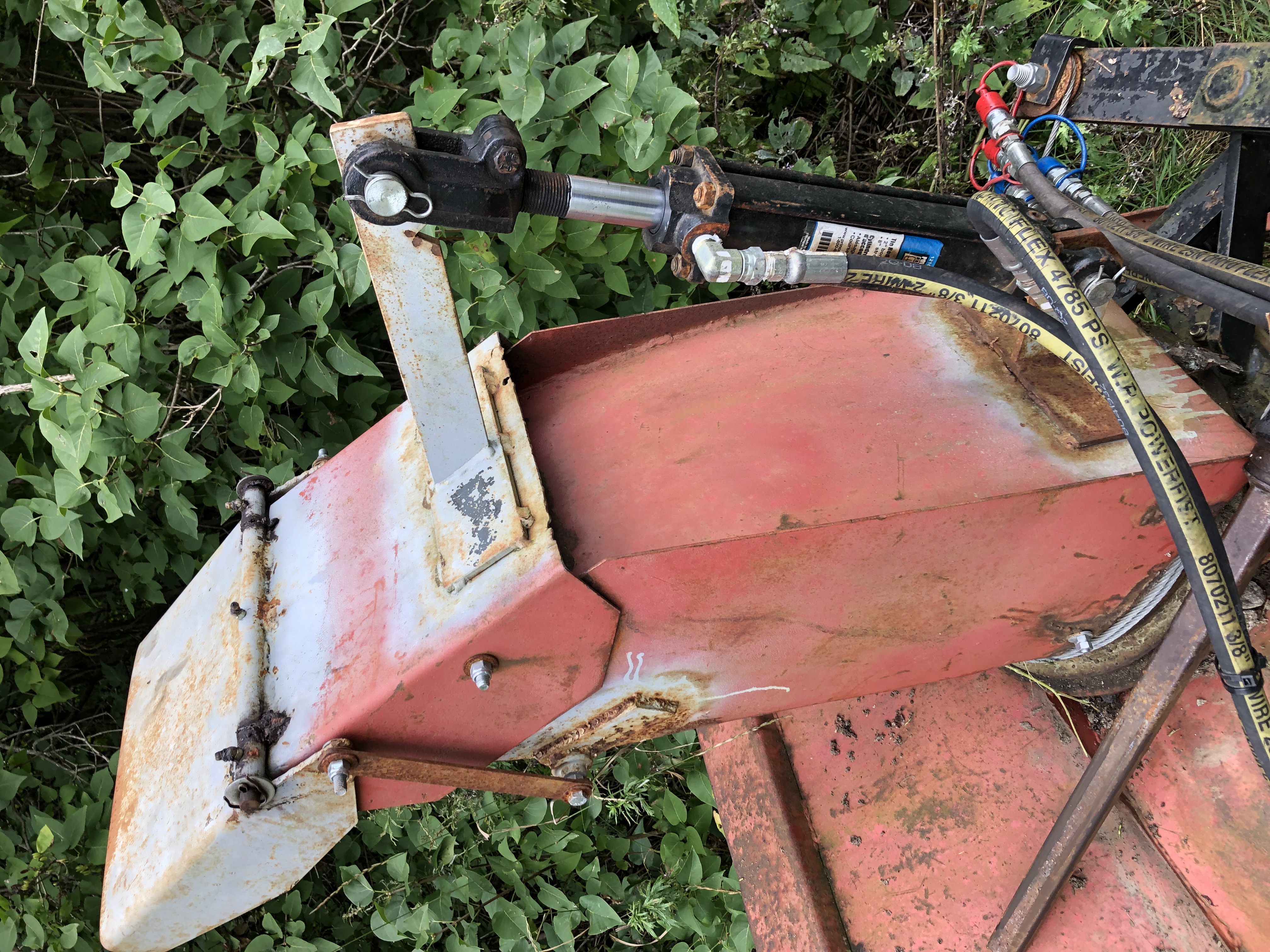
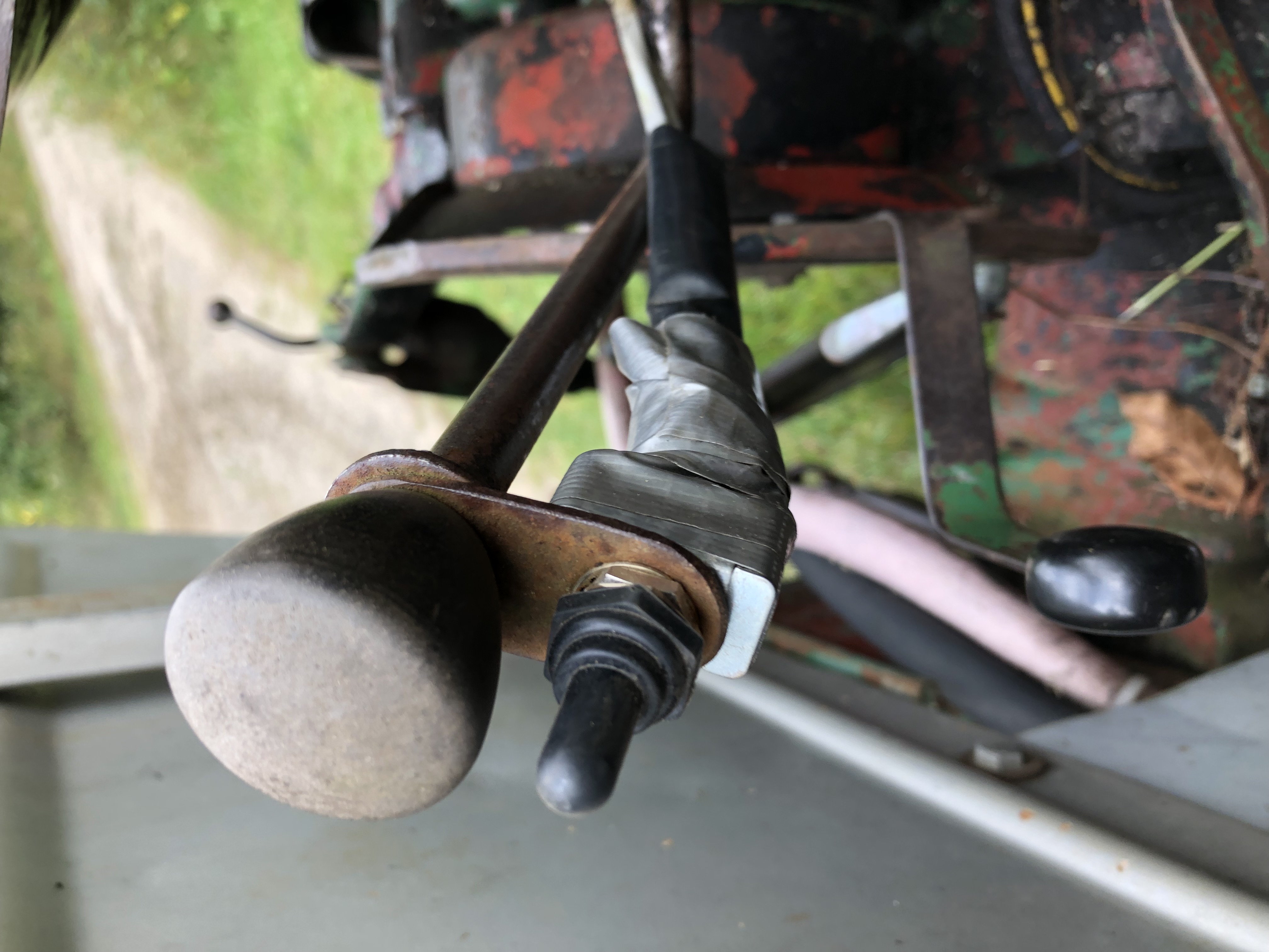
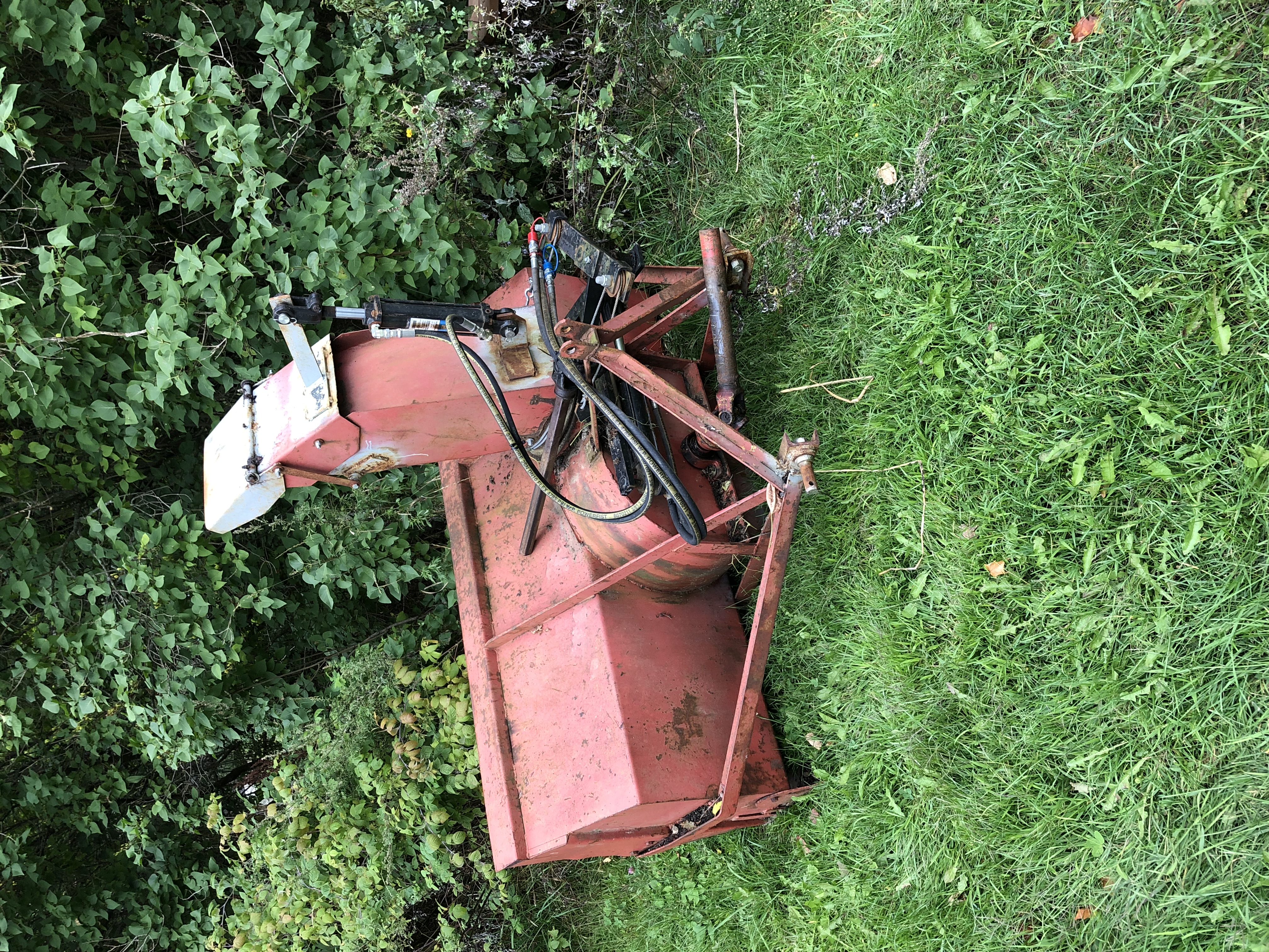
The tractor was used a lot with the implemented device. One day I might stumble upon a video of it in operation and decide to post it here. Meanwhile, here are a few photos of the setup. Please don’t mind the color palette too much, this was meant to be a work horse on the farm, not a beauty pageant winner ;-)
Don’t forget to subscribe in the chat and comeback soon!