FX's Projects
Musings involving electronics, systems, and stuff hackers care about.

ESP32 port: better flow and temp sensors
Here is a recent one. The code is in this github repo. It should be made available soon.
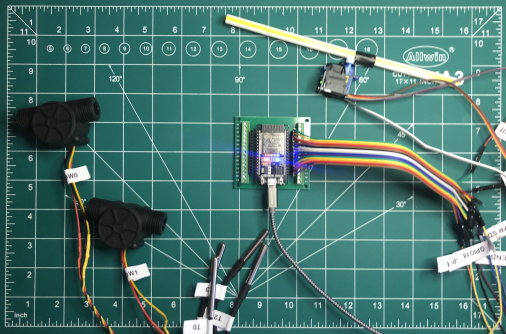
This is the story of the refactoring of a double flow rate and quadruple temperature sensing MCU on bare metal. It interfaces through gRPC on serial to a fast API backend and out to the web. An IMU and a servo were also added, for reasons that will become apparent later.
When exposing sensors on the internet, this setup is common and effective. Running bare metal on the MCU comes with a few responsibilities and one could argue that an RTOS could have been a sensible choice here. For this system though, free cycles were simply used to integrate the inertial platform and a servo to form a tight PID loop that turned very useful for debugging. More on this later. In hindsight, there would have been ample space for an RTOS. So, that seed is planted now.
Let’s first describe the system in its first iteration as a viable IoT interface and for this first jot in C++.
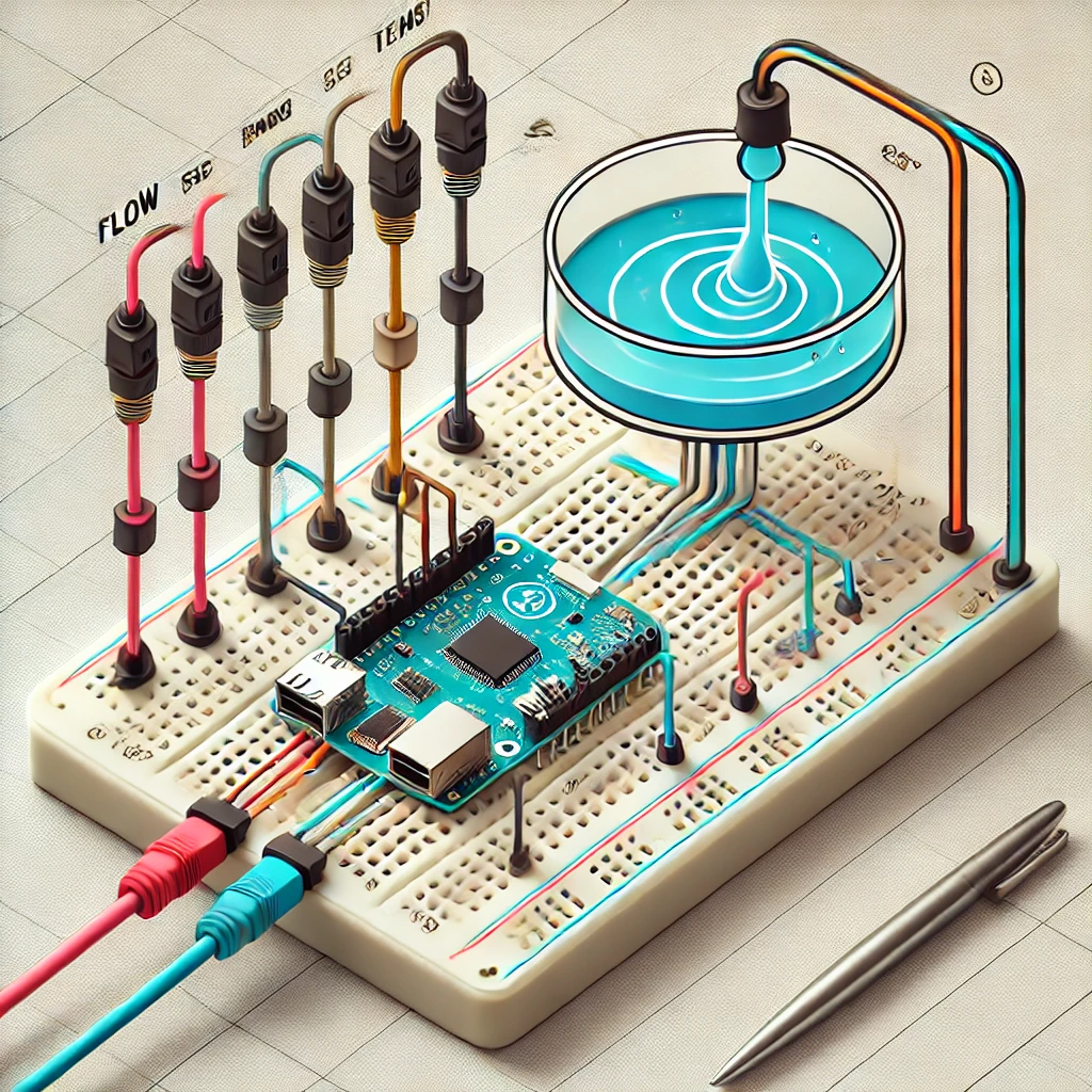
General concept
The system is comprised of sensors (IN), actuators (OUT) and Computing elements. The link between the ESP32 and the backend is over serial at 115 200 Baud and the backend exposes the API over https.
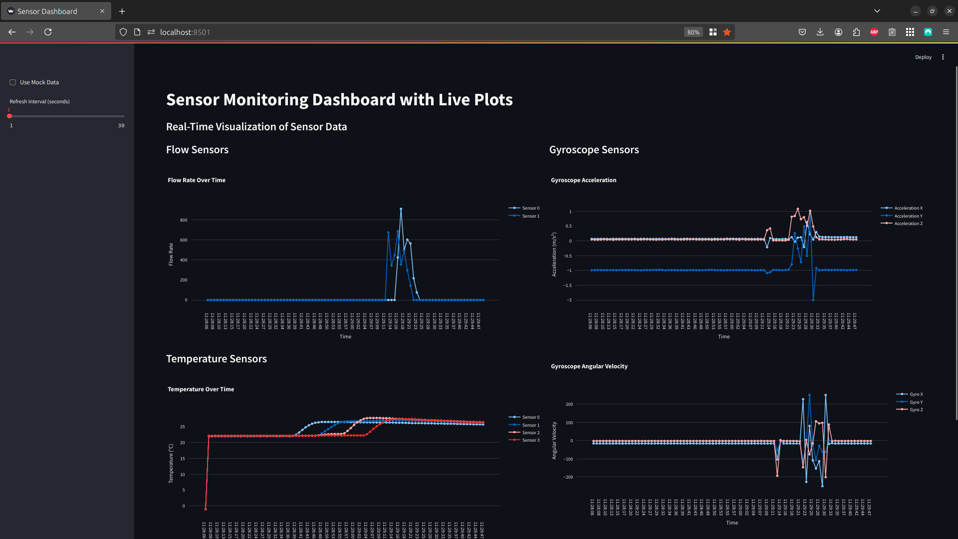
Not represented in the drawing, but shown in the screenshots above, is a minimal Streamlit application that displays live data.
graph LR
    subgraph IN
        A[T0 to T3]
        B[Flow0]
        C[Flow1]
        D[IMU]
    end
    subgraph OUT
        K[Servo]
    end
    subgraph Compute
        G[esp32s3]
        H[Backend Server\nFastApi]
        I[The Web]
    end
        A <--> G
        B --> G
        C --> G
        D <--> G
        G --> K
        G <--> H
        H <--> I
Desired features
The refactor had to:
- Serve the gRPC protocol to interface with the backend
- Implement the full resolution from an arbitrary number of digital temperature probes
- Measure 2 liquid flows with constant minimal resolution
- Maintain a very clear identification of:
- any connected device (multiple ESP32 could be present on the USB bus)
- a build id
- an API version
- Free up sufficient computing power to maintain a PID loop in function with very smooth operation
Software architecture
Before diving into deeper system details, let’s have an overview of the main software components. The tool chain used is PlatformIO but the Arduino framework was kept as it enabled a very quick integration path with librairies that were known to work well with the interface to the temperature sensors’ 1-Wire protocol, the servo using PWM on timers, the IMU on I2C and the backend on serial.
The idea here was to provide a solid first interface with the least amount of effort. And that worked.
Main structure
The App class is a classic setup() and loop() interface and serves as a main entry point. The setup phase enables installing various interrupt routines and configure the GPIOs of the device. The loop serves all the objects periodically and waits for updates on timed or interrupted events.
Sensors
The class hierarchy of the project was elaborated to represent sensors and control elements. The sensor class was derived the most, with the definition of a FlowSensor, a TemperatureSensor and a GY521Sensor.
The abstraction of a ControlElement was thought to be a good base to elaborate filters, PID controllers and general signal handling black boxes. The initial intent was to develop a registry and to enable the composition of signal chains. While implemented from the beginning, the idea was left aside temporarily and to prioritize the basic functionality.
The IMU, based on a Kalman filter, was implemented using the gyro sensor as an input and abstracted independently to provide sensor fusion. The gyro used has 6 axis: acceleration and velocity respectively for the x, y and z axis.
A PeripheralManager class is in charge of setting up all sensors and configuring the chip.
Interfaces
The gRPC interface was abstracted and isolated from the rest of the code with a module named simpleRPC. While perfectly functional, its interface is through function pointers and, thus, is behaving more like a C library. The solution to properly use it was to keep all of the interfacing in one class and through the use of static members. Protocol Buffers was briefly considered but left out for future improvements.
While looking a tad like a kludge, this works without too much problem as soon as the various parameter passing schemes were validated. It turns out that an Object< > structure is the best abstraction to encapsulate data between the MCU and the backend. The backend itself runs in Python/FastAPI with a port of the simpleRPC protocol.
The device exposes its mac address through a get_device_info member that is dynamically populated at run time. The same function also returns a git_version and a build_version that are carried from the build and the CI/CD process.
Build and CI/CD process hooks
The ./scripts path contain build scripts that perform a few tasks, including populating a ./include/_build_uuid.h with a build hash that is uniquely replaced every time a new build is performed while ./include/_git_version.h contains a macro that defines the latest commit hash. These values are passed to the ESP32 as compile time constants.
Two important hooks are built in the repo to populate header files to bring version information to the binary.
Improvements
Many improvements ideas have accumulated and a fair amount of code refactoring will start soon. The current object diagram looks like this:
 graph TD
    App
    QuickPIDController --> ControlElement
    IMU
    InterfaceManager
    PeripheralManager
    ServoController
    Timer
 graph TD
    LogEntry
    Logger
    PIDConfig
    FlowSensor --> SensorBase
    GY521Sensor --> SensorBase
    TemperatureSensor --> SensorBase
IMU and channels
The IMU should probably be refactored as a SensorBase element with 6 outputs and be lined up with the other sensors. This would be a good opportunity to generalize sensors with the concept of channels, an idea that is present also in the temperature sensors all living on a 1-Wire bus.
SensorBase and access method
Sensors also exhibit various little quirks in their preferred access methods. This, in itself, is sufficient to call for a refactor of the SensorBase class in order to properly model the behaviors. The benefits will be many, as more sensors are anticipated to enter this code base!
For example, the temperature sensors have to be triggered to produce updated measurements. These measurements could require up to 1 full second to be ready for serial access on the bus using their unique addresses. The approach taken was to expose a trigger route through the API to let the user of the sensor decide when to trigger a new conversion. This is silly, at best, and very inefficient.
Two important features also emerge here that were not modeled in the current version of the code: triggered measurement and uniquely identified measurements. A few other ideas also made their way to a clearer set of characteristics for the sensors. Summing them up, we can think of:
- sensors that require configuration
- sensors that require a trigger to start processing
- sensors with polled outputs
- sensors that interrupt the system to provide an update measurement
- sensors that interrupt the system to provide a new piece of information, eventually leading to a measurement
Actuators also produced at least one unanticipated challenge:
- the imported Servo class will stop producing the PWM signal no update is sent, requiring a test to the object before attempting to send a command.
All this to say that a DeviceBase class could be used to represent SensorBase and ActuatorBase, that they should probably abstract away the communication interface with simple periodic calls and support multiple channel devices. It should offer an interface to get the physical property being interfaced, its units (both of these already in this code base), but add a range for update frequency and abstract away the complexity of getting data from or to the device. Now that we are on the subject, specific devices could benefit from block access for higher bandwidth or specific tests.
Meta thinking
This series of reflections on the design are probably one of the most important benefits of proper architectural design while following SOLID principles in object oriented programming. Thinking about how you can groups stuff to abstract it away makes you think about unique versus common characteristics, behaviors and quirks.
All of these attributes of the sensors were known before the project started. Only when trying to line them up into a model that such interesting properties and ways of thinking about abstract concepts pop out of the problem and make the task of writing the code a very satisfying experience! Of course, it has to serve a purpose and, in this very precise case, I am writing about it instead of having written the code: the trade offs were in favor of making the thing work first ;-)
Guess what will happen now?
The status
The time frame for this project was very limited. The first refactoring to the ESP32 was thus running in parallel with the design of an FPGA interface to an hdmi display project. Almost as if it was a mule or a test bed.
The servo and the IMU are currently used as a feed point for a roll angle to modify the rotation of a set of test bars on the hdmi display. The PID loop maintains the straw attached to the servo level with the ground and the IMU data is sent from the ESP32 to a raspberry PI playing the role of a deluxe level shifter for serial communications but is also expanding the serial data into a proprietary serial packet protocol to interface with registers in the FPGA.
All 4 temperature sensors, the 2 flow sensors and the 6 IMU raw values (acceleration and gyroscope rotation rate) are sent to the Streamlit interface in real time and update the display.
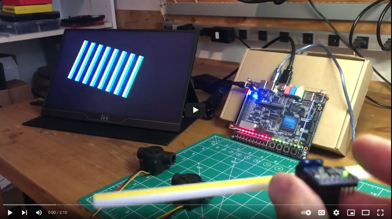
(If you don’t see the thumbnail: click here to start the video of the experiment demo)
So we reached the goal of reconnecting everything. We have an access mechanism to 2 flow sensors and 4 1-Wire temperature sensors, while maintaining a proper communication channel with a backend interface. The live data updates to the FPGA driven display came in later, but blended in very gracefully.
The current software implementation is very easy to extend, but a few key refactor will make it more SOLID and easier even to refactor. This is currently in the works.
I’ll also come back to present the device identification, build id and git version information. The algorithm used for the flow calculation is also interesting, same thing for the Kalman filter (although this one is of a rather basic vanilla flavor here…).
So, in summary: as this projet became a shim layer between a backend in python/FastAPI and firmware in a FPGA that is still under development, it became quite clear that the framework is very useful in my lab. Consequently, more content and documentation here is bound to follow…
Don’t forget to subscribe in the chat and comeback soon!
Afterthoughts
2024-12-18 TODO: Wouldn’t it be nice if a standard C++ library would already provide generalized interface to sensors? This must be already solved for IoT, right?
Let’s take a look at this first:
- lm-sensors
- SensorFusion
- ThingSpeak
- Zetta
- Adafruit Unified Sensor Library
- Mbed OS
2024-12-19 TODO: Have you seen Kieran Borovac’s video, Seven Dimensions ? It dives into vectoring and generalizing unit system representations. If you’re familiar with OpenFOAM or full physics simulation, you’ve likely encountered this concept before.
It got me thinking about a potentially exciting feature for a sensor class. Let’s see how this evolves… 🚀